Features and their dialogs
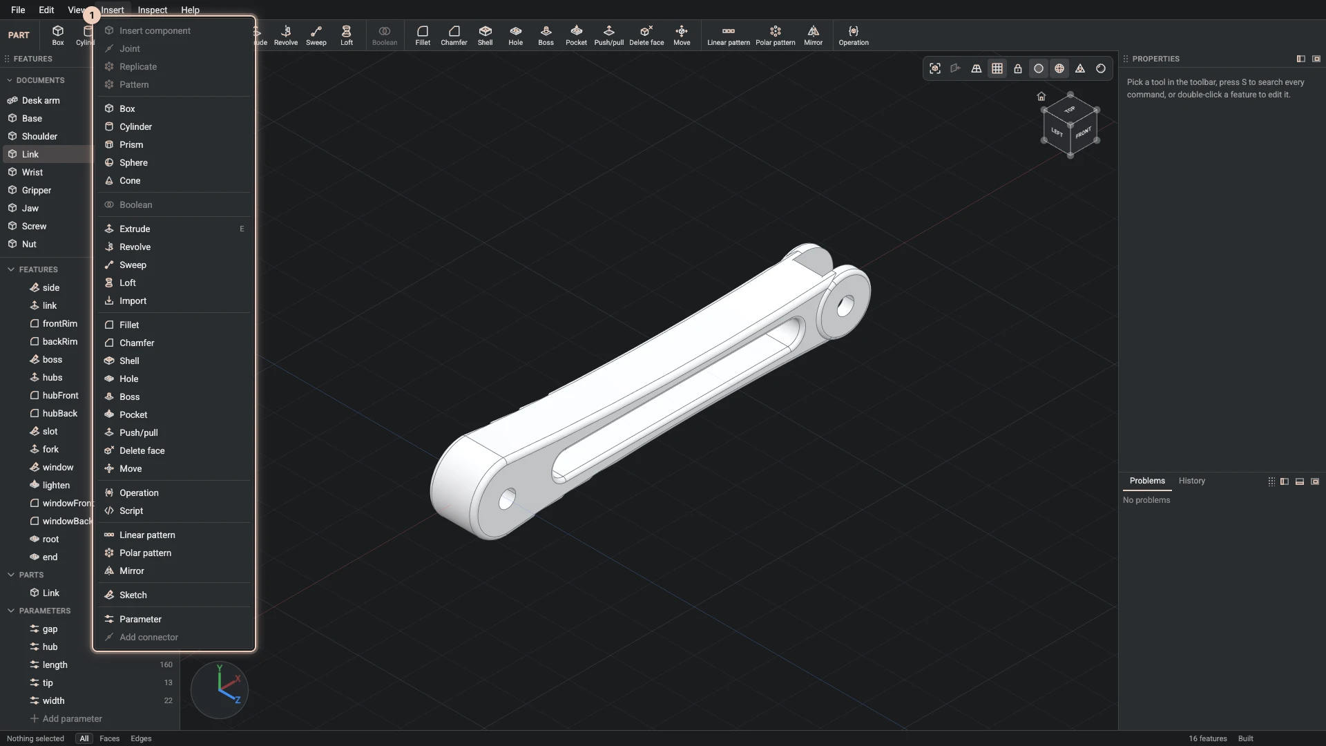
A part is a list of features, built in order. You add one from Insert or the toolbar, fill in its dialog, and OK adds it after the features already there.
How a dialog works
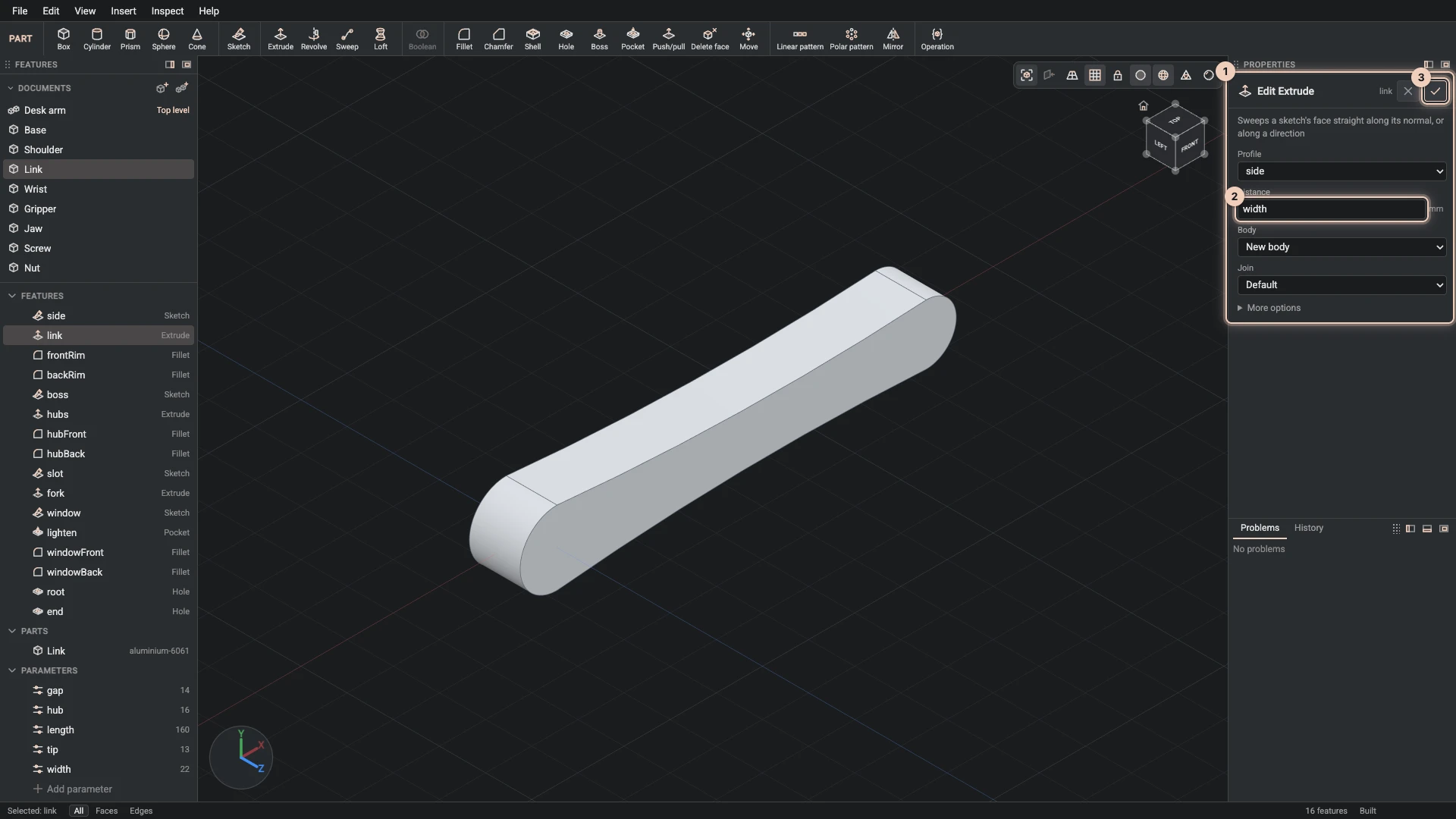
A feature's dialog opens in Properties, with a line on what the feature does and its fields under it. The picture shows the desk arm link's extrude.
- Numbers take expressions. Type a number, or an expression of the part's parameters such as
widthorlength / 2 - 8. The field keeps the expression, so the feature follows the parameter. - Picks come from the view. A field that needs faces or edges, such as a fillet's Edges, asks you to click them in the view, then says how many are picked; Clear starts again. You can also pick first: the Selection panel then offers the commands that take what you picked, and their dialogs start with it.
- What it still needs is written in the dialog in orange, and OK waits until nothing is missing.
- The view previews the feature as you change it, and shows handles you can drag where a value is a distance or a position.
- More options holds the fields most features leave as they are.
- OK (Enter) adds the feature; Cancel drops it.
To change a feature later, right-click it in the Features panel and choose Edit feature. The same dialog opens as you left it, and OK rebuilds everything after it.
Bodies
The features that make shape start a new body, named after the feature, unless you choose one in Body. With a body chosen, Join says what happens to it: the new shape is added to it (Add), cut from it (Cut) or intersected with it (Intersect). The features that change shape, such as a fillet, always work on the body you name.
Solids
Box, Cylinder, Prism, Sphere and Cone make a whole solid from one dialog, standing on a plane or rising from a flat face you picked. Each is a sketch and an extrude or a revolve underneath, so its faces have the same names as if you had drawn it. A part with no features yet offers them in the middle of the view, beside Start a sketch on the ground.
Gear makes an involute spur gear the same way: a Module for the size of its teeth, how many Teeth, a Thickness and a Bore, the hole through its middle. Two gears of the same module mesh when their centres are half the module times their teeth added together apart, so a 20-tooth and a 30-tooth gear of module 2 sit 50 apart. Its sketch keeps the teeth as one Gear pen command, where the pressure angle, the backlash and the rest of the tooth's shape can be changed, and its side faces are named by the part of a tooth they belong to: tip, flank or root. A feature that takes edges can name them by those parts, such as a chamfer on the edges round every tip and nothing else.
Ring gear makes a gear with its teeth on the inside, as in a planetary set: its Module, its Teeth, a Thickness and the Rim outside the teeth. A gear of the same module turns inside it with its centre half the module times the difference of their teeth from the ring's, so a 20-tooth gear sits 40 from the centre of a 60-tooth ring. A ring needs at least 34 teeth, so their tips stay outside the circle the involute starts from.
Features that make shape
| Feature | What it does |
|---|---|
| Extrude | sweeps a sketch's face straight out by a Distance; E |
| Revolve | turns a sketch's face about an axis, a whole turn or by an Angle |
| Sweep | sweeps a closed sketch along an open one, its Path |
| Loft | skins a solid through two or more sketches, in order |
| Import | starts a body from a STEP, IGES or BREP file the document carries |
Features that change shape
| Feature | What it does |
|---|---|
| Fillet | rounds the Edges you pick to a Radius |
| Chamfer | bevels the edges you pick by a Distance |
| Shell | hollows a body to a wall Thickness, leaving the faces you pick open |
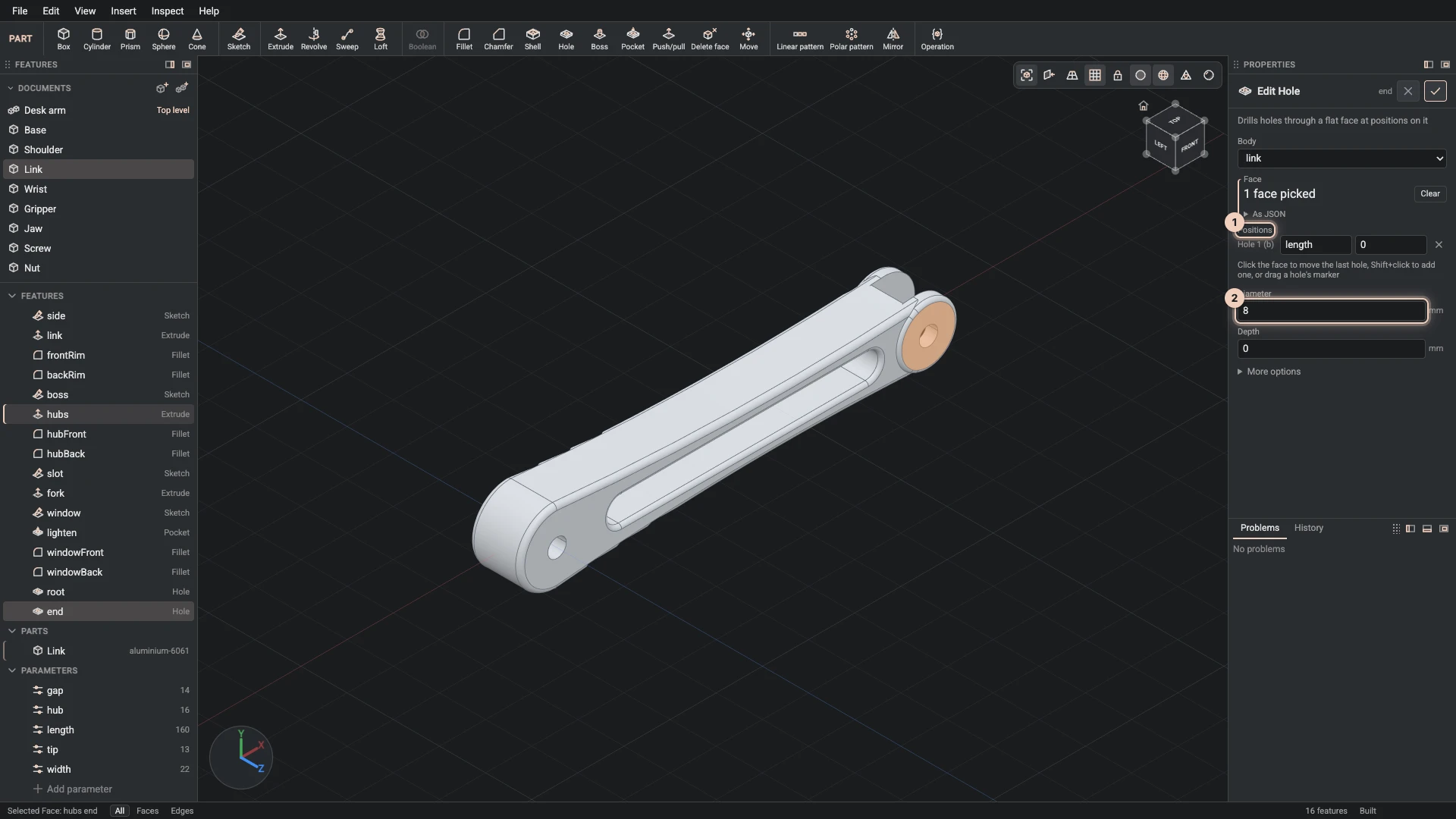
| Hole | drills holes into a flat Face at Positions on it, through or to a Depth, with a counterbore or a countersink if you like; a Fastener sizes them for a screw instead of a Diameter: pick its Standard, ISO metric or ANSI inch, its Size, an inch screw's Series and the Fit, a close, normal or loose clearance or tapped for its thread; Counterbore for a socket head sinks a socket head cap screw, and Fasten then reads it all |
| Boss | raises a sketch drawn on a face out of it |
| sinks a sketch drawn on a face into the body, by a depth or through it | |
| Push/pull | moves a face out or in, the faces around it following |
| Delete face | removes faces, such as a round or a hole, and closes the gap |
| Move | moves and turns a body as one piece |
A hole shows a marker for each position. Click the face to move the last hole there, Shift+click to add another, or drag a marker; the picture shows the hole at the end of the desk arm's link, whose position is written in its length parameter.
Machining shafts and bores
Six features in the Insert menu cut standard machining into a round face: pick a shaft's side or a bore's wall as the Face, and each sizes itself for that face's diameter.
| Feature | What it does | Its faces are named |
|---|---|---|
| Keyway | mills a DIN 6885 or ANSI B17.1 keyway into a shaft, or cuts one through a hub's bore, over a Length | keyway |
| Flat | takes a flat a Depth deep off a shaft, such as the one a set screw bears on | flat |
| Ring groove | cuts the groove a DIN 471 or inch retaining ring sits in on a shaft, or a DIN 472 or inch ring in a bore | groove |
| Knurl | knurls a shaft in a straight, left, right or diamond Pattern, at a DIN 82 pitch or an ANSI B94.6 Diametral pitch | knurl |
| Spline | cuts DIN 5480 involute spline teeth of a Module into a bore, or ANSI B92.1 ones of a Pitch such as 16/32 and a number of Teeth; drill the bore to where the hub's teeth end, or give the Reference diameter | spline |
| Thread | models an ISO metric thread, or a Unified inch one, on a shaft of its size or in a bore drilled for its tap; the Size, such as M8 or 1/4, is found from the diameter when left empty | thread |
Each cut starts From the end its distance along the face's axis. The axis points along the world axis nearest it, and the end it starts from is the one it points away from, so a shaft standing on the ground is measured from its foot; From the other end measures from the far end. A keyway or a flat faces world X, or world Y on a shaft that lies along X, and its Angle turns it from there. Each of these but the flat has a Standard, and in an inch design it starts on the inch one (Units and inches); every length is in the design's unit, whichever standard it is. A face that is not round, a flat or knurl on a bore, a spline on a shaft and a thread on a diameter no size of its standard has are refused with the reason, so the feature turns red rather than cutting something else. A modelled thread is heavy to build and draw; keep it to the parts that need it, and leave the rest to the cosmetic threads of the standard parts.
Combining bodies and patterns
- Boolean combines a body with others, its Tools, by Union, Difference or Intersection. The tools are used up.
- Linear pattern repeats a body in a row, Polar pattern around an axis, and Mirror across a plane; the copies are fused with it. To repeat whole parts in an assembly instead, see component patterns.
Anything else the kernel can do
Operation runs any operation of the CAD API by its dotted path, such as occt.operations.offset, with its inputs, and keeps the result as a feature. Script runs a script the document carries on the part's geometry. Both are rebuilt like any other feature.
Verified against the product in October 2026