Components and sub-assemblies
An assembly document has no geometry of its own. It places parts from part documents as components, and other assemblies as sub-assemblies, then holds them together with joints. Start one with File > New assembly.
Insert a component
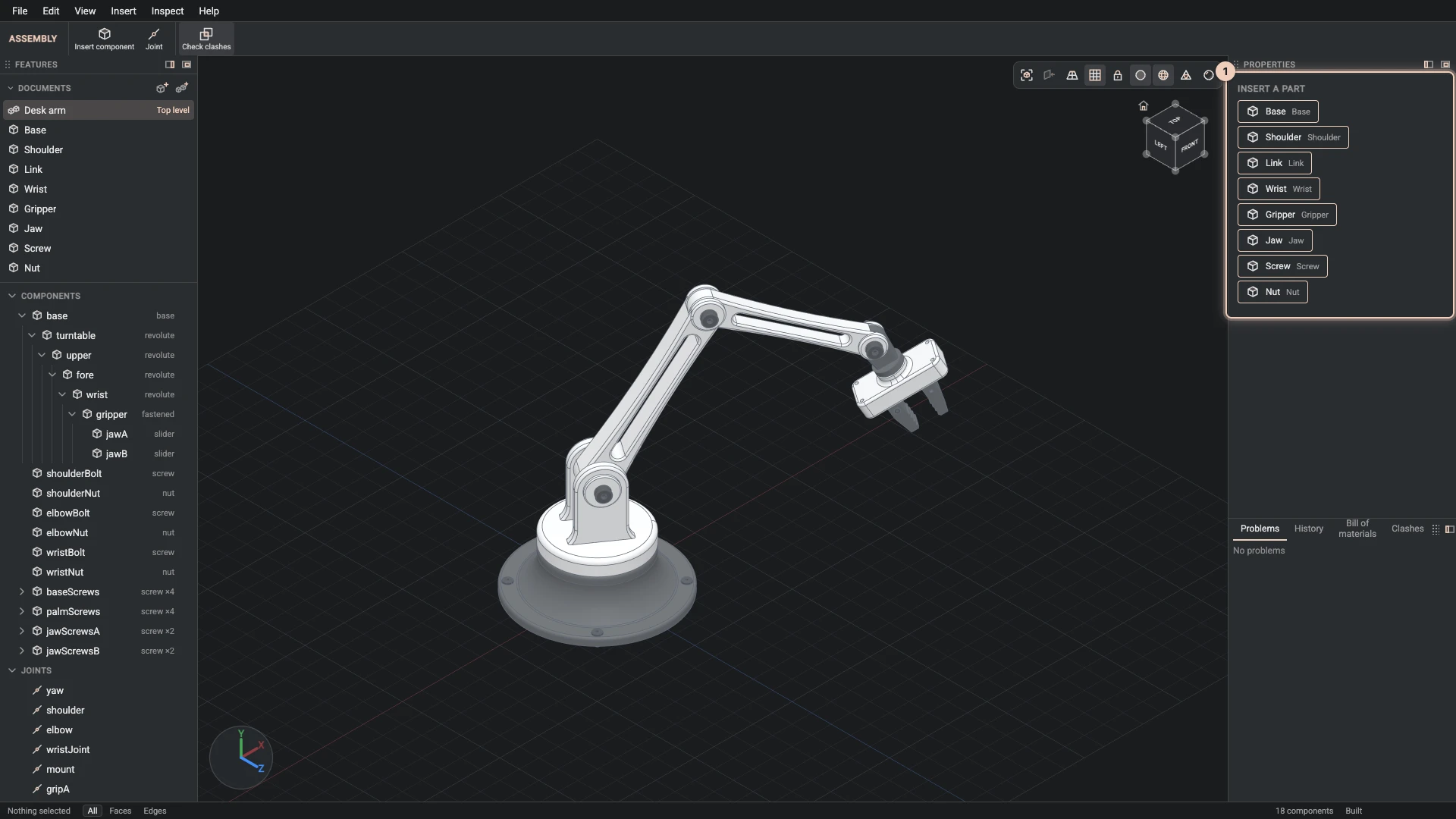
Choose Insert > Insert component, or the toolbar button. Insert a part in Properties lists every part of the project's part documents, and every other assembly; click one to place it. It lands beside what is already there, ready to be joined. An assembly that places nothing yet offers Insert component and Import STEP, IGES or BREP in the middle of the view.
One part document can be placed many times, and in many assemblies. The bill of materials counts each placement. Insert > Insert again places another of the part you placed last, with the same sizes.
Drag a part into the view
Drag a part document from the documents list, a part or an assembly from Insert a part, or a tile from the standard parts library onto the view. While you drag, the part lies on the face under the pointer, standing on it the way it stands on the ground, or on the ground where no face is under it, snapped to the grid. Drop it there.
Dropped onto a face that holds a connector of the part under it, it joins that connector with its own first connector in the same change: the view shows it already joined before you let go. Two axes, such as a nut on a washer, make a revolute joint; anything else is fastened. Hold Alt while dropping to place it free, without a joint. One undo takes the part and its joint away together.
Copy, paste and duplicate
Select components in the tree or the view, then Ctrl+C (⌘C on a Mac) to copy them and Ctrl+V to paste them into this or another assembly of the design, or Ctrl+D to duplicate them at once; the Edit menu has the same. Each copy keeps its sizes and its pattern, stands beside where the original stood, and gets a new id. Joints are not copied: join the copies as you need.
An assembly of chosen parts
Choose part documents in the documents list with Ctrl or Shift, right-click, and choose New assembly from these: a new assembly places their parts side by side, and chosen assemblies as sub-assemblies, and opens. On one document's row it makes an assembly of that one.
Standard parts
Insert > Standard part, or Standard part in the start view, opens the library in Properties: Fasteners, Gears, Bearings and springs and Keys and rings. Choose a part, then its Standard where it has more than one: fasteners and ball bearings are ISO or ANSI, keys and retaining rings DIN or ANSI, and an inch design starts on ANSI (Units and inches). Set its sizes, every length in the design's unit. The view shows it as it will be made, and every size is checked the way the kernel checks it, so one it would refuse is named before anything is added. In a part document, Add as a part document makes a new part document of it and opens it; in an assembly, the button inserts it beside what is already there.
Each part is one feature that the kernel's standard parts build, sized by its parameters, with its connectors on the faces that part names:
| Part | Sizes | Connectors |
|---|---|---|
| ISO 4762 socket head cap screw | size (M1.6 to M24), length, modelledThread | seat, under the head |
| ISO 4014 hex bolt, or ISO 4017 threaded to the head | size, length, fullyThreaded, modelledThread | seat |
| ISO 4032 hex nut | size | seat, top |
| ISO 7089 plain washer, or ISO 7090 chamfered | size, chamfered | seat, top |
| Set screw with a hex socket | size, length, point (flat, cone, dog or cup) | top, on the socket end |
| ISO 8734 dowel pin | diameter, length | end |
| ASME B18.3 socket head cap screw | size (#0 to 1), series (UNC or UNF), length, modelledThread | seat |
| ASME B18.2.1 hex cap screw | size (1/4 to 1), series, length, fullyThreaded, modelledThread | seat |
| ASME B18.2.2 hex nut | size | seat, top |
| ASME B18.22.1 plain washer | size, series (narrow or wide) | seat, top |
| ASME B18.3 set screw | size, series, length, point (cup, flat, cone, oval or half dog) | top |
| Spur gear | module, teeth, width, bore, keyway, keyStandard (DIN or ANSI), hub, hubLength, pressureAngle, profileShift, backlash | axis, on the face it stands on |
| Helical gear | as the spur gear, and helixAngle and herringbone | axis |
| Straight bevel gear | module, teeth, mateTeeth, shaftAngle, faceWidth, bore, pressureAngle, backlash | back, on its axis |
| Ring gear, teeth pointing in | module, teeth, width, rim, pressureAngle, backlash | axis |
| Rack | module, teeth, width, height, pressureAngle, backlash | back |
| Deep groove ball bearing, rings, balls and cage | designation (623 to 6210), shields | inner and outer, on the rings' sides |
| Compression spring, ends closed and ground | wireDiameter, diameter, activeCoils, length | bottom, top |
| DIN 6885 parallel key | shaftDiameter, length | bottom |
| DIN 471 or 472 retaining ring | kind (shaft or bore), diameter | side |
| R-series inch ball bearing | designation (R1-4 to R20), shields | inner and outer |
| ANSI B17.1 square key | shaftDiameter, length | bottom |
| Inch retaining ring | kind (shaft or bore), diameter (1/8 to 2 inches on a shaft, 1/4 to 2 in a bore) | side |
The yes-or-no options are boxes in the library: modelledThread models the thread's helix instead of drawing it, which is slower to build; fullyThreaded, chamfered and shields choose the standard's other form; keyway cuts a keyway into the bore, sized by its keyStandard, which needs a bore its table holds: over 6 mm for DIN, over 5/16 inch for ANSI. An assembly keeps one document for each kind and standard: every component of it sets its own sizes and options, and the part number, such as ISO 4762 M8x25, ISO 4017 M8x30 or SHCS 1/4 UNC x 1-1/4, follows them into the bill of materials. Threads are drawn at the screw's full diameter and named, not cut, so a screw in its tapped hole or nut touches it without overlapping; the clash check leaves out a thread resting on a thread, whether or not a joint holds the two. A spring's length set by an expression of the assembly's parameters compresses it as the parameter that drives its joints changes. Fasten puts screws in a hole set in one step.
Two spur gears of the same module mesh when their centres are half the module times their teeth added together apart. Join each by its axis to the part it turns on with a revolute joint, and give the joints' angles from one parameter, such as turn: the first turn, the second the other way by the ratio of their teeth, with 180 divided by its own teeth added so the teeth fall into each other's gaps. For 20 and 30 teeth that is turn and 180 / 30 - turn * 20 / 30.
A component's own sizes
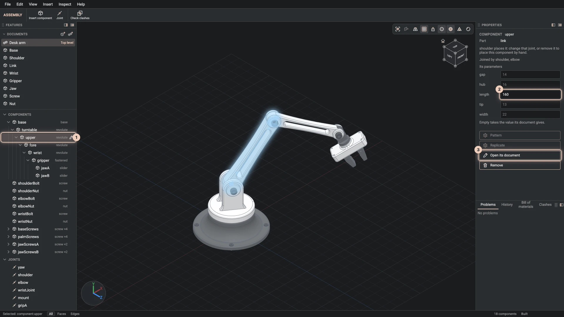
The Components group nests each component under the one a joint holds it to, with the joint's type beside it, so the tree reads like the assembly's chain. Select a component there, or click it in the view, and Properties shows it:
- the part it places, and the joints that hold it;
- Its parameters: the part document's parameters, each left empty to take the document's value or given this component's own. A choice, such as a screw's
size, offers its list, and a yes-or-no option offers Yes and No, each with the document's value first; a number can be an expression of the assembly's parameters, so one assembly parameter can size several parts.
The picture shows the desk arm's upper arm: a component of the link document with its own length, 160. The forearm places the same document shorter and slimmer, at a length of 130 and a width of 14.
Move a component
A component that no joint places can be moved: the gizmo in the view moves and turns it, and At in Properties takes its position exactly. A component a joint places says so, and moves when the joint does; change the joint, or remove it, to move it by hand.
Sub-assemblies
Place an assembly document the same way, and it becomes a sub-assembly: one component that carries its own components and joints, and moves as one. The jet engine is built this way: its two spools, the two halves of its casing and its stand are sub-assemblies of the top one. A sub-assembly's rows fold open in the Components group.
In the view, a click picks the top-level component; Select one level deeper goes down through each sub-assembly to the part.
Change the part itself
Open its document opens the part document a component comes from, with that part selected, to change its features. Every component of that document follows when you come back.
Remove a component
Select the component in the tree or pick it in the view and press Delete, or right-click it and choose Remove component; Remove at the foot of its Properties does the same. The joints that hold it go with it, and Ctrl+Z brings both back. The right-click menu on a component also copies, duplicates, opens its document, patterns and replicates it, and on two selected gears offers Mesh gears; a selected joint is removed the same way.
Hide a component
To see past a component, select it (or pick it in the view) and press H, or right-click it and choose Hide; it leaves the view with everything inside it, and its row in the tree turns grey and says it is hidden. Right-click a hidden component's row in the tree and its menu offers Show in place of Hide. Show only these hides every other component instead; right-click the ones left showing and the same place in the menu reads Show all. While anything is hidden, the status bar at the foot of the window counts it beside a Show all button, which, like Shift+H, brings every hidden component back. Hiding only changes what the view shows: the design, its clashes and its exports keep every component, and opening another document shows everything again.
Verified against the product in October 2026