Joints
A joint puts one component's connector onto another's and says how the component may move there. The first component is placed by the joint: move the joint, and the component and everything joined to it follow.
Add a joint
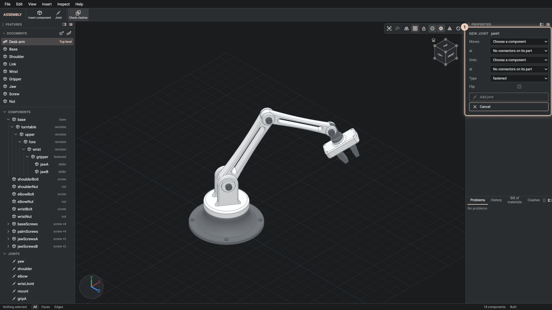
Choose Insert > Joint, or the toolbar button. New joint opens in Properties:
- Moves: the component the joint places, and at which of its connectors.
- Onto: the component it is joined to, and at which connector there.
- Type, below, and Flip to turn the component over on the shared axis.
- Add joint.
A component lists only the connectors its part has; one without any says so, and Connectors shows how to add them.
The four types
| Type | The component may |
|---|---|
| fastened | not move: it is fixed there |
| revolute | turn about the shared axis, like a hinge |
| slider | slide along the shared axis |
| cylindrical | turn about the shared axis and slide along it |
Angle, offset and limits
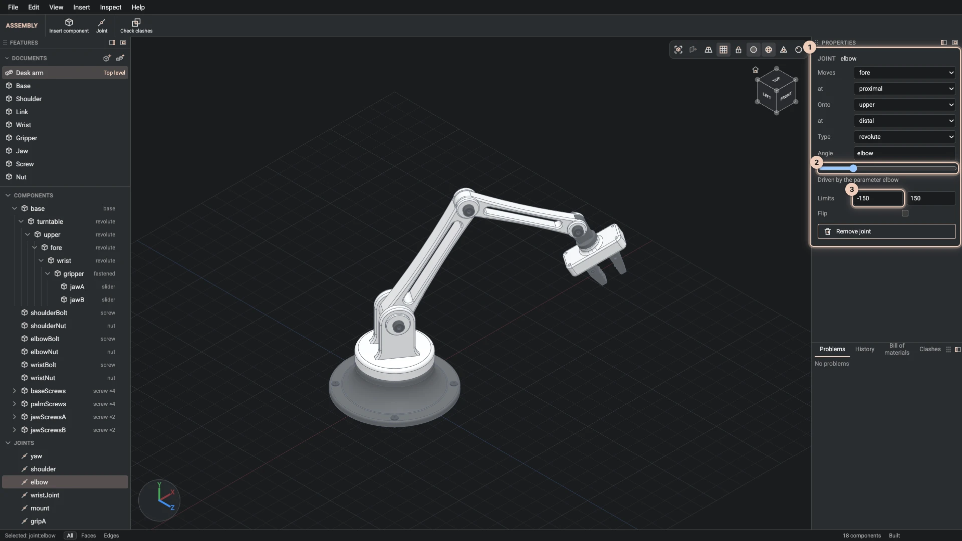
Select a joint in the Joints group to see it in Properties. A revolute joint has an Angle, a slider an Offset, a cylindrical joint both, each with a slider to try it:
- Limits say how far it may go, the least and the most. The slider stays within them.
- Driven by a parameter. Write a parameter's name, or an expression, as the angle or the offset, and the joint follows the parameter. The picture shows the desk arm's elbow, driven by its
elbowparameter within ±150°.
Remove joint takes the joint out; its component stays where it is and can then be moved by hand.
Mesh two gears
Two gears drive each other only when their teeth interlock - they mesh - and that takes three things at once: their centres the right distance apart (half the module times their teeth added together, for standard gears), the teeth of one sitting in the gaps of the other, and the second turning the other way, slower or faster by the ratio of their teeth. Mesh gears does all three. Select two spur gears from the standard parts in the tree, the one that drives first, and run it from the Insert menu:
- each gear gets a revolute joint about its axis, the driving one where it stands, the driven one moved towards where it stood to the distance the pair needs;
- both joints are driven by one angle parameter,
turn, added when the assembly has none, so draggingturnturns both gears together, their teeth in mesh all the way round; - the two gears must have the same module and pressure angle. If their teeth would cut into each other's flanks, the command still meshes them and says so (
interferes).
The joints are written with the teeth counts the gears have now; mesh them again after changing one.
Pose the assembly
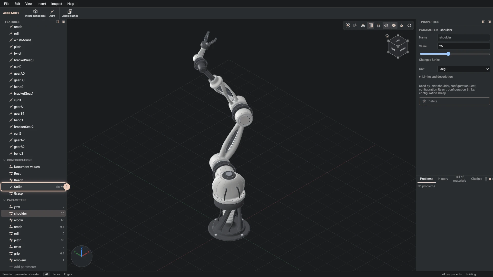
With its joints driven by parameters, the whole assembly poses from a few numbers: drag a parameter's slider and the chain moves. A configuration keeps a set of those values under a name, and clicking it in the Configurations group builds the assembly that way. The robot arm from the showcases keeps its rest, reach, strike and grasp poses as configurations.
Parts that meet at a joint are expected to touch there, so the clash check leaves those touches out.
Verified against the product in October 2026